 GRXEL
GRXEL
Traffic cone spacing looks like easy arithmetic until a number from a search result lands on a field sheet with no source beside it. The familiar “one times speed in a taper, two times speed on a tangent” rule is real. It is not a complete traffic-control layout, though, and it is not written as a federal Standard.
This guide starts with the current federal source: the FHWA MUTCD 11th Edition with Revision 1, dated December 2025. It is meant to help buyers and estimators read a plan and prepare a clearer equipment request. It does not design, approve or modify a temporary traffic control (TTC) plan. The governing agency's current manual or supplement, project documents and approved plan control the work.
If the immediate question is cone height, base, sheeting or packing rather than layout, use the separate bulk traffic-cone and channelizer sourcing guide. Spacing and device specification belong in the same request, but they are different decisions.
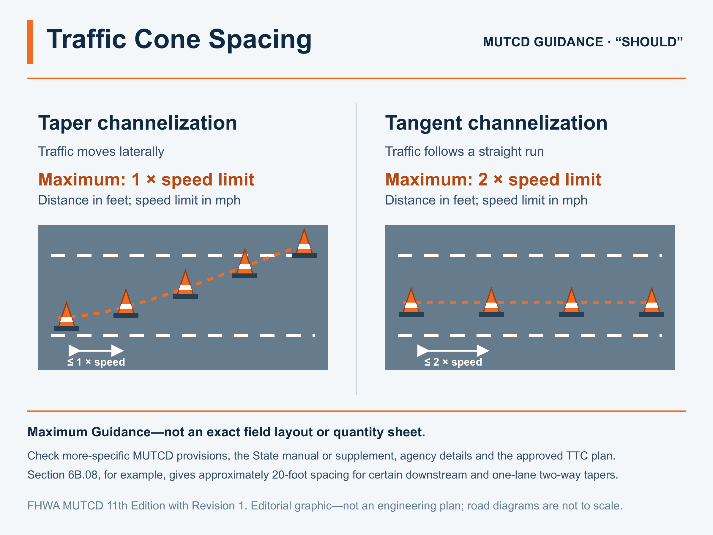
The federal baseline is easy to remember—and easy to misuse
Section 6K.01, Paragraph 4 of the complete current MUTCD PDF gives this Guidance for cones, tubular markers, vertical panels, drums and barricades:
| Segment | Federal Guidance maximum | A 35 mph screening example |
|---|---|---|
| Taper channelization | Distance in feet should not exceed 1 × the speed limit in mph | 35 feet maximum |
| Tangent channelization | Distance in feet should not exceed 2 × the speed limit in mph | 70 feet maximum |
Those figures are maximums under the general federal Guidance. They are not an instruction to place every cone at exactly that distance. A plan can bring the devices closer together, while a more specific MUTCD provision or a State or agency document can control the interval used on the job.
There is another important distinction. Section 6K.01 labels device crashworthiness as a Standard: channelizing devices shall be crashworthy. The spacing paragraph is Guidance: spacing should not exceed the stated values. Both statements matter, but they do not carry the same meaning in the Manual.
“Should” and “shall” are not interchangeable
The MUTCD defines its headings in Section 1C.01. A Standard is a required, mandatory or specifically prohibitive practice and typically uses shall. Guidance is recommended practice for typical situations and typically uses should; a deviation needs appropriate engineering judgment or an engineering study.
Calling the 1×/2× language “the law everywhere” misses that distinction. Dismissing it as “just a suggestion” is no better. It is federal Guidance in the national Manual, and the responsible agency and traffic-control professional have to treat it accordingly.
State requirements can be more prescriptive. FHWA's FAQ on State MUTCDs and supplements explains that a State can make a national should condition a shall condition or narrow an optional practice. The current 23 CFR 655.603 also addresses substantial conformance and says State supplemental documents—including policies, directives, standard drawings and specifications—cannot negate national Standard or Guidance statements.
That is why “MUTCD spacing” is not enough on a purchase request. Ask which edition, State adoption or supplement, agency detail and approved plan apply to this location on this date.
Taper spacing and tangent spacing describe different geometry
A taper moves traffic laterally out of or back into its normal path. A tangent is the comparatively straight channelizing run after the transition, often alongside the work space. Mixing the two can double a spacing value in the part of the layout where it does not belong.
Spacing is also not taper length. Section 6B.08 treats taper length separately, with the appropriate length based on taper type and the criteria in its tables. A merging taper, shifting taper, shoulder taper, one-lane two-way taper and downstream taper do not all use the same length.
The same section shows why the general 1× value is not a universal layout table. Its Guidance calls for approximately 20-foot device spacing on a 50- to 100-foot downstream taper, and likewise for a one-lane, two-way traffic taper. When a more specific provision fits the situation, do not overwrite it with the general screening formula.
Use the chart to catch obvious takeoff errors
The arithmetic below applies Section 6K.01's general Guidance. It is useful for spotting an estimate that deserves another look. It cannot choose the speed input, identify the segment, set the endpoints or replace a plan.
| Speed limit stated for the spacing check | Taper Guidance maximum | Tangent Guidance maximum |
|---|---|---|
| 20 mph | 20 ft | 40 ft |
| 25 mph | 25 ft | 50 ft |
| 30 mph | 30 ft | 60 ft |
| 35 mph | 35 ft | 70 ft |
| 40 mph | 40 ft | 80 ft |
| 45 mph | 45 ft | 90 ft |
| 50 mph | 50 ft | 100 ft |
| 55 mph | 55 ft | 110 ft |
| 60 mph | 60 ft | 120 ft |
| 65 mph | 65 ft | 130 ft |
| 70 mph | 70 ft | 140 ft |
Notice the wording in Section 6K.01: the spacing calculation refers to the speed limit. Other Part 6 calculations can define their speed input differently. For example, the taper-length criteria in Section 6B.08 discuss posted speed, the pre-work off-peak 85th-percentile speed or anticipated operating speed. Do not move an input from one calculation into another because both happen to use mph.
When the plan pulls the devices closer together
The general maximum is only one boundary. Closer placement might be selected or required where the plan has to deal with:
- A downstream or one-lane, two-way taper covered by the more specific Section 6B.08 Guidance.
- Curves, crossroads, driveways, ramp openings or a short urban block.
- A temporary alignment that needs stronger visual continuity.
- Channelizing devices being used with or in place of temporary pavement markings.
- Pedestrian or bicycle movements that require a separately designed, detectable route.
- Night work, glare, fog, snow, visual clutter or a history of devices being displaced.
- A State supplement, agency standard drawing or contract detail with a tighter value.
These are reasons to check the plan, not automatic reduction factors. The person responsible for the TTC plan evaluates the actual conditions. The buyer records the resulting value and its source; the quote desk should not improvise one.
Count from the plan, one segment at a time
A dependable takeoff starts by marking every channelized segment on the approved drawing. Label each as a taper, tangent or other specifically defined segment, and write the plan spacing beside it. Put the plan revision and controlling detail on the quantity sheet as well. Otherwise, a clean-looking total can hide a bad assumption.
Do not simply divide total road length by one spacing value. Adjacent runs might share an endpoint device; a taper may have a plan-specific count; openings may interrupt the line; and extra devices can be called out for transitions, driveways or replacement stock. Rounding and endpoint rules belong on the takeoff, not in someone's memory.
Before requesting prices, capture:
- Governing agency and the current State MUTCD, supplement, standard drawing and specification references.
- Approved TTC plan number, sheet, revision and approval date.
- Speed value used for each calculation and where that value came from.
- Each segment's type, measured length, stated spacing and required device count.
- Device class, height, color, reflective treatment, base or ballast and any accessory shown in the documents.
- Daytime, nighttime and duration conditions.
- Required crashworthiness and agency-acceptance documentation for the exact configuration.
- Delivery sequence, pallet quantities, replacement stock and the inspection/repositioning plan.
The traffic cones and channelizers category can help organize the hardware shortlist after those fields are known. A 28-inch traffic channelizer example and a 42-inch channelizer-cone example also show why “orange cone” is not a complete line item. Verify the exact offered size, sheeting, base and documentation against the project requirements; neither page approves a device for a particular layout.
Where cone counts go wrong
| Mistake | Why it fails | Better check |
|---|---|---|
| Treating the federal maximum as the required exact gap | Guidance says “should not exceed”; it does not say every gap must equal the maximum | Use the approved plan value and record its source |
| Applying tangent spacing through a taper | It can double the general screening value in the transition | Classify each segment before calculating |
| Treating spacing as taper length | They are separate dimensions governed by separate provisions | Record taper type, taper length and device spacing in separate fields |
| Ignoring State and agency documents | They can be more prescriptive or supply a specific standard drawing | Verify the current jurisdictional stack before takeoff |
| Counting by total length ÷ spacing | It can miss endpoints, shared devices, interruptions and specific counts | Take off each plan segment and show rounding assumptions |
| Assuming the product name proves acceptance | Size, bands, base, crashworthiness documentation and agency rules still matter | Review the exact submitted configuration |
Give the supplier the plan-derived answer, not the puzzle
A supplier can price the hardware, freight and documents more accurately when the request already contains plan-derived quantities. Include the delivery location and date, exact device configurations, bases, reflective bands or sheeting, accessories, packing preferences and submittal requirements. Mark an unresolved technical field pending. A catalog description should never fill it by accident.
GRXEL can help match an available configuration to a defined request. Send GRXEL a project RFQ with the plan references and takeoff. Final layout and acceptance remain with the governing agency and responsible traffic-control professional.
What should end up on the takeoff
By the time the count is ready to sign, the sheet should show which rule or plan note controls each segment. If Section 6K.01 applies with a 45 mph speed limit, 45 feet is the general federal Guidance maximum in the taper and 90 feet is the corresponding maximum on the tangent. Those are ceilings under that general provision, not default installation intervals.
The 1×/2× relationship still does not supply taper length. Section 6B.08 deals with taper types and length criteria, while Section 6K.01 supplies the general channelizing-device spacing Guidance. Keeping those two fields separate prevents a plausible-looking number from migrating into the wrong column.
Total road length does not produce a dependable purchase quantity either. The count needs approved segment lengths and types, spacing values, endpoints, interruptions, plan-specific counts and the replacement-stock policy. If one of those inputs cannot be traced to the current plan or governing document, leave it pending instead of filling the gap with a remembered rule.